Nixie clock with ESP8266 and DS3231
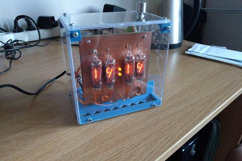
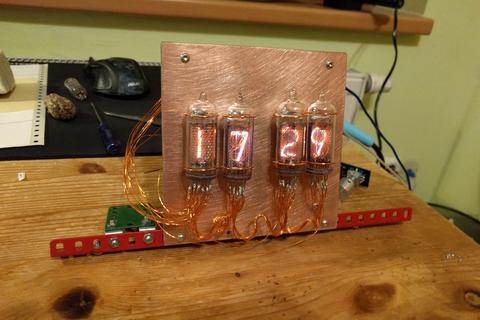
2018-01-21This is a livingroom clock with four IN-14 nixie tubes, NodeMCU/ESP8266, DS3231, complete with an acrylic case held together by 3D printed components (STL models included).
Why get a nixie clock?
Nixies have an undeniable charm to them. They're cool. But my primary reason for making a nixie clock was a practical one: I wanted a clock which would provide great visibility and legibility any time of the day or night. Nixies are a perfect fit for that. Even my myopic eyes can see the digits both at night and with sunlight coming in through the windows. (Unfortunatelly though, my phone's camera isn't very good at capturing glowing nixies. It looks better in real life compared to some of the photos.)
Getting nixies and cathode drivers
Nixies can be ordered from E-bay. I ordered a bunch of them from Ukraine. The shipping time was around 3 weeks (I live in Czech rep.) and they arrived in a perfect condition, wrapped in bubblewrap, all fully working and with long enough pins. 5 stars, would buy again :)
The cathode drivers (74HC141 being the most famous one) are specialized logic circuits capable of working with the high voltage coming in from the nixie cathodes. They were manufactured where I live some decades ago and people still have them around in surprisingly large quantities. I found such a person through E-bay and arranged a meeting with them in the city. It felt like buying pot, but the goods were again in a perfect condition and there was no shipping cost.
Worldwide, these drivers can probably be bought the same way as the nixies themselves, you just need to remember you need them as well. Apart from the Czech republic, these drivers were also manufactured in the USA, Russia, and perhaps elsewhere too.
The microcontoller
Pretty much my whole reason to use the NodeMCU module was that I wanted to try out the ESP8266. I'd heard good things about it. It's like an Arduino but with more CPU power and RAM (and obviously there's WiFi capability). I opted for the NodeMCU module as the easiest and most convenient way to interact with the ESP.
The electronics
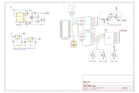
I copied most of the analog electronics from elbastl.sweb.cz. The 170V power source is copied verbatim and the anode drivers are modified to accept 3.3V voltage levels by lowering the gate resistor to 6k8. (Unlike Atmels and similar uCs, the ESP8266 operates at 3.3V.)
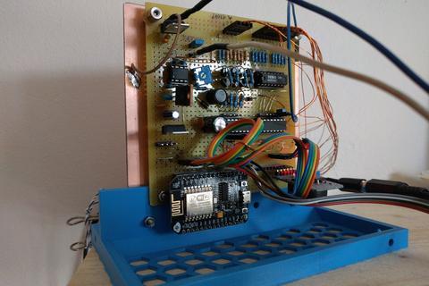
As for the digital parts, they all revolve around the ESP. Since it doesn't have terribly many GPIO pins, I decided to use a pair of serial-to-parallel shift registers in a cascade. That way 3 of the ESP's digital pins expand to 16 output pins (and potentially more if more registers were added to the cascade, as long as timing allows). Both anode and cathode drivers are connected to the registers as well as some status LEDs.
Some care needs to be taken to ensure correct voltage levels. The 74HC141 is old fashioned and operates at TTL levels. It requires 5V voltage supply unlike the ESP, but it accepts 3.3V logic levels on inputs just fine. I used a pair of 74HC595's as the shift registers, which is a CMOS logic IC, which means it needs to be on the 3.3V branch in order to accept levels from the ESP. (Alternatively, I suppose one could use 74HCT595 as well.)
Care also needs to be taken while testing the circuit or its parts. The 170V voltage source used in this circuit is not dangerous for a human (to my best knowledge), but it is dangerous for other electronic components, especially ICs. I learned this the hard way when I accidentally touched the 170V pin and a pin of one of the IC's with the same finger. While I didn't feel a thing, it burned the IC.
The time source
The ZS-042 RTC module is in fact the actual clock. It features the famous DS3231 module. The ESP talks to the RTC module over I2C.
I also considered leveraging the builtin WiFi feature to synchronize time via NTP, but I figured setting up WiFi credentials would be a lot more complex than setting the time itself by hand and that it simply doesn't pay off. And so for the time being the WiFi part of the ESP remains unused.
Programming
The source code is in C using the native Espressif SDK and is fairly simple. The program first initializes all internal structures and hardware configuration, then sets up two timers and enters a sleeping loop. The firmware takes care of calling the timer callbacks. The first timer takes care of displaying the digits (one at a time), it operates with a period of about 0.8ms. The other timer download time from the RTC every once in some 135ms. (These number are chosen to prevent flicker, but they are fairly arbitrary to be honest.)
Inputs are taken care of with interrupts. I had to add some software-level corrections to make up for the poor quality of the KY-040 rotary encoder module (it's very cheap).
Interaction
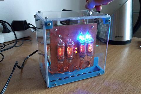
I wanted the clock to be controlable with just one physical knob. A rotary encoder with a builtin button is a natural choice for that. One press of the knob switches the clock to a setup mode. There's a blue LED behind each of the nixies. First, the hour part of the display is backlit by the LEDs and knob rotation sets the hour count, and then another press switches to the minute part. A final press of the knob saves the current time into the RTC and returns the clock to the default state.
Physical setup
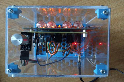
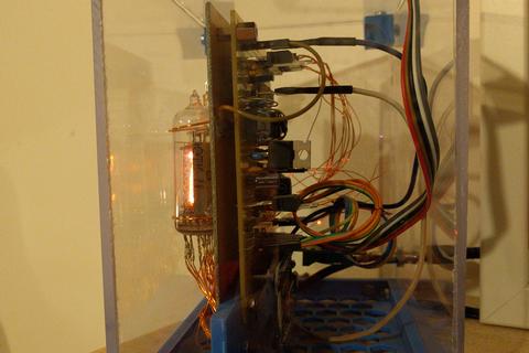
A ready-made universal PCB has been used for the circutry (one with alternating horizontal and vertical lines, purchased in local boffin shop). The nixies are mounted with copper wires (and a bit of gluegun glue) on another PCB, one with no etching, just plain copper covering. They are connected with a bunch of thin (0.4mm) enameled copper wires. I had to cut and de-enamel ends of more than 40 of these short wires, which was time-consuming and boring, but the result looks fairly cool, if I say so myself.
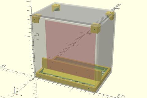
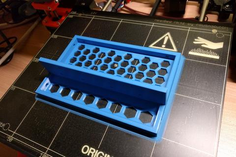
Both PCBs are mounted vertically on a 3D-printed base, with the display PCB facing front and the circuit PCB in the back. The whole thing is surrounded with pieces of acrylic held together by screws in the base and a set of four small 3D-printed corner pieces. I used OpenSCAD to design these pieces and a Průša pinter to print them out. The rotary encoder knob is mounted through the top acrylic piece.
The whole thing looks like a bit like a weird steampunk fishtank. The only thing I'm not satisfied with completely are the acrylic pieces; they were cut with a lot of imprecission as at the time I didn't have the right tools to do that. The edges are somewhat wavy and rough. But luckily this is only visible from up close and doesn't really affect the overall look and feel.
Github repo with code & documentation: github.com/vojtechkral/nixie-clock
